

Lineofsight wrote:Albert H wrote:jax wrote:
As 3 mtr jim stated the pll transmitters stephen sold evolved from a vfo exciter that operated at quarter of the frequency with a pll that was programmed with wire jumpers, this then evolved into the 50meg version with virtually the same pll circuit with a few improvements such as dip switch frequency selection way before paul hollings got involved.
A bit later on, I helped with the further evolution of the PLL PRO III. It was my suggestion to use the 74HC4059, because we wanted to get away from using a "programming chart" and the BCD code inputs (and the lack of a reset period) would allow a move to BCD rotary switches (when he'd used up all the DIP switches!). These would have directly shown the selected frequency. I also designed a frequency display for the rig - which would have been the first NRG product to contain a PIC! I also added the OLPD to the board layout, so that the output was switched off (by raising the emitter voltage on the driver stage).
I redesigned his little PRO III stereo coder so that it knew its left from its right, and the input sockets on the board could be correctly labelled. I also added the facility to switch to mono, and the two LEDs (to match the PRO III exciter) which indicated mono and stereo. The modifications radically improved his old basic product and made it sufficiently different from the "Veronica" thing (that didn't know its left from its right and put big spurs out 4.684MHz either side of the carrier because of the poor board layout).
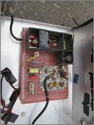
The PRO IV Stereo coder was my design. It was something I'd been playing with for a while, and Stephen wanted a new product that would made his range stand out more from the charlatan down the street. I took a Veroboard prototype up there, and Stephen and I spend a day laying out the PCB. We etched and drilled a couple of prototypes, and populated the boards with the ICs I'd brought along for the purpose. One minor improvement to the design involved a cut track and an earth strap (to reduce a tiny hum), and we were astonished by how good the thing sounded. The measured results were amazing - the noise, distortion, separation, phase accuracy, and frequency responses (and lack of spurs) were all superb. They even got sold to a lot of professional, commercial broadcasters, and they are still in widespread use in many countries in their 1U 19" rack version with balanced audio inputs.
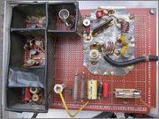
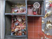
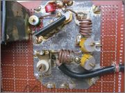
Stephen's oscillator was a dual Hartley type, derived from the "Kallitron" oscillator developed in the 1930s (by Cheirix and Mesney), and had a number of things to recommend it. Even without the PLL, it was quite stable, and if the capacitors were carefully chosen, and the coils made from sufficiently stiff wire, it would largely stay put. The big bonus was that it was "self-doubling" and developed the Band II signal when the two oscillators were cross-coupled. There's a sort of "current robbing" phenomenon going on, and the two oscillators inherently synchronise themselves with the right phase relationship to double their basic frequency. It also has the benefit that the highest frequency the PLL has to sample will be 54 MHz. This can easily be counted by cheap 74LS TTL ICs. The output of the oscillator was fed through a highpass filter to eliminate any small ½f content that could otherwise leak through due to minor component tolerance imbalances. Steps were taken in the component selection and in the board layout to ensure the closest balance possible.
Another innovation of mine was to use FETs to do the sampling from the oscillator, and we also experimented with diode switching of capacitors into the oscillator (selected by the 4059 programming lines) to select the part of the band the oscillator was going to. This eliminated the trimmers altogether, but never went into production.
Incidentally, if you short the two bigger square pads beneath the 2SC1947 with a piece of flat copper braid (taking care not to short anything else out) you'll increase the gain of the final stage and the board will give >5 Watts ight across the band.
Incidentally, there's a subtlety in the driver stage - it doesn't give the same power out across the band. The final needs a few extra milliwatts at 108 and fewer at 87.5, so a gain slope was introduced to the driver to flatten out the output power.
The Hollings rubbish never managed the performance of Stephen's gear. Hollings lost in court (I was an expert witness), and it cost him a lot of money. We demonstrated that Stephen's designs actually were his, and that the Hollings products were just poor, cut price copies with very inferior performance.
Unfortunately, Stephen also had to pay out a lot in legal fees as there were no costs awarded.
As an end user the PLL 3 is awesome. Hands down best bit of radio gear I have owned. Respect.
I have the 40W PA board attached and with a SWR of 1.1: it runs as cool as a cucumber with no fan so I do not believe the higher power rigs would have been a problem at all. Steve and Albert obviously know what they are doing.
Users browsing this forum: THE FIRM, WeaponX and 2 guests


