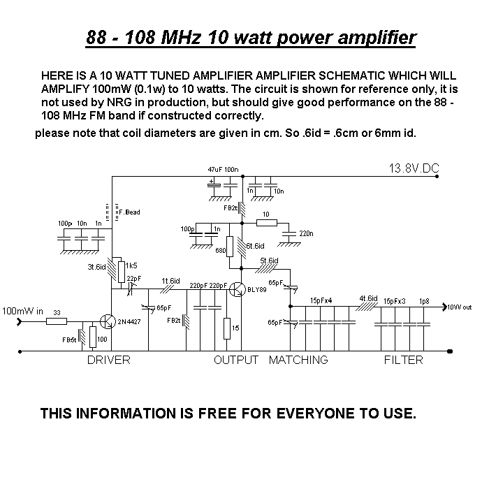
10 Watt RF Amplifier schematic for use on the 88 to 108 FM Wavelength
If you have a low power FM Transmitter
of around 50 - 100 mW (.05 to .1 Watt), this amplifier will boost the
power to between 8 and 14 watts output.
This 10 Watt RF Power
Amplifier uses the Philips BLY89C Transistor for the output and a 2N4427
driver stage. Because the output transistor is fully rated for 25 watts
output minimum continuously, this circuit design is very robust and
will tolerate very high SWR mismatch.
You must use a small cylinder
type heatsink on the driver transistor and of course a reasonably
substantial finned heatsink for the BLY89C. Under normal operating
conditions, about 5 watts of heat may be generated by the amplifier
final device (BLY89C) and this is why the finned heatsink is necassary.
This Amplifier uses tuning capacitors to maximise the power output and
give maximum RF gain. There is an inherent advantage to using tuned
stages in that the output signal is quite pure without additional
filtering. Stability from spurious low frequency oscillation is provided
by the damping resistors in the Transistor Base and Collector circuits.
It is important to use brand new Trimming Capacitors when undertaking
any Tuned RF Power Amplifier project. Second hand trimming capacitors
can be bad news, as they can only stand an infinite number of adjustment
cycles, and may be already shot when you fit them! The coils can be
made out of readily available copper wire. Silver plated wire is not
necessary at this power level and frequency.
A correctly working unit will need a power supply that can provide a
solid 12 volts (or 13.8 volts) dc at a current of at least 1.5 amps.
Therefore, most CB power packs will be ok. But a 300 mA Wall Adapter
most certainly will not!
