The 'Pantek' ---The worst 3-watt FM transmitter ever built
."Professional Transmitter, Varicap controlled stability" said the advert for this piece of self oscillating junk!
Here is one of the worst FM broadcasting transmitter
kits I have ever come across, probably THE worst. The thing below has
sold thousands since it came along in the 1980's. You may have seen
one, with the name'PANTEK' stamped on it. They sold for around �20-00
and looked like value for money.
The transmitter is basically just a power oscillator, based around
T3 and T4, a pair of 2N3553's oscillating (and drifting) strongly in
push pull mode at some frequency between 88 and 108 MHz. Using just
a fundamental frequency power oscillator (no driver, no output stages!)
is just about the worst method of transmitter design because of the
following points.
1. The frequency can be 'pulled' several MHz by any change in aerial
loading (windy wet days=lots of drift)
2. The oscillating transistors T1 and T2 get very hot, and so cause
frequency drift of several MHz.
3. The circuit board has no ground plane! Promotes all kinds of unwanted
additional spurious signals.
4. The frequency will drift by several MHz with supply voltage changes.
Although rated at 3 watts rf power output, you would rarely see
more than half a watt. The worst thing was that so many spurious frequencies
were present, you didn't really know which was the main signal. The
designer of this
'VHF power oscillator' circuit has never been identified.
The above circuit diagram shows the audio pre-amplifier on the left, a conventional dc coupled cascade 2 transistor amplifier. The 'low' input would work with a microphone and the 'high' input was for line level input, i.e. a cassette player. The transmitter section is to the right and this shows the cross coupling from outputs to inputs with C8 and C9. T3 and T4 would get very hot and often failed, mercifully halting the transmission.
This picture above shows the printed circuit board. Note there is no groundplane!!!!

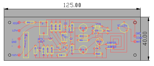
And this it, above, the component layout of the infamous 'Pantek' 3-watt fm transmitter! It was a small transmitter pcb, measuring just 121mm x 44mm. It was sold as a kit to build yourself and some people actually claim to have got the thing working successfully. If you want to build one, the parts list is provided below!
Resistor list: Capacitor list: Semiconductors: Specs
R1 100K C1 22uF 16V D1 4001 Power supply: 12-15V
R2  100K        C2  22uF 16V        T1  BC549           Current:         0.5A

R3   47K        C3  22uF 16V        T2  BC549           Frequency:       80-108Mhz

R4  220K        C4  0.047uF         T3  2N3553          Input:           10mV / 1V

R5    1K        C5  1nF             T4  2N3553          Arial impedance: 75 Ohm

R6   47K        C6  10pF            D2  VCD ITT BB139
R7   15K        C7  27pF

R8  2.2K        C8  27pF            T3/T4 need heatsinks

R9   10K        C9  0.047uF
R10 100K        C10 22uF 16V

R11 4.7K        TR1 2-18pF, red

R12  10K        TR2 5-65pF, yellow

R13 4.7K

P    10K