Powerful Medium Wave AM Broadcasting Transmitters
The pictures below show various installations at Brookmans Park in the UK
 |
|
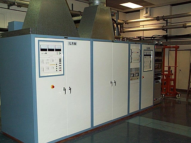
BBC RADIO 5 MW AM TRANSMITTER (150 kW) The above photograph shows the three 50 kW Doherty AM transmitters used by BBC Radio 5 at the Brookmans Park site. The output of these are combined into a Triplexer to achieve 150 kW of RF power. These are tube transmitters and each uses 2 x 4CX35000 tetrodes. The Anode voltage is 17000 volts dc at high current. The audio is applied to the tube screen grids for modulation. These Doherty transmitters are made by the Marconi Company, model B6034. They were installed in 1978 and still look brand new because they use valves instead of transistors. |
 |
|
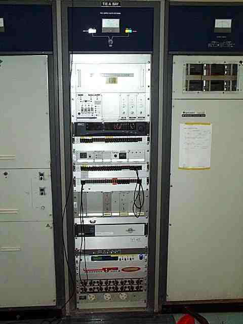
BBC RADIO 5 TIE BAY The TIE bay is mainly made up of the Optimod 9200 processor, the AM6/18 (delay type) limiter (BBC Designed), the HCD signal sources and the reserve programme feed (Radio 5 from Astra Digital), main programme feed is from Broadcasting House via BT Musicline. Another reserve is ISDN which is rarely used. |
 |
|
SUNRISE RADIO AM TRANSMITTER (50 kW) The London Asian station Sunrise Radio uses 1 x 50 KW , Nautel XL60 transmitter and 1 x 12 kW Reserve transmitter, these are modular and use Pulse Width Modulation into a RC circuit to gain the AM signal. They use a Optimod 9200 processor with an Optimod 9100 as backup. Kilostream is the main programme feed with Astra Satellite backup. |
 |
|
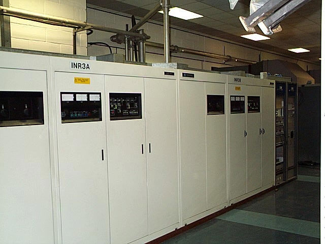
TALKSPORT AM TRANSMITTER (100 kW) Here is a fairly up to date AM transmitter design from the Harris company, recognized by many as the leaders in transmitter design and manufacture. There are no tubes here because TalkSport uses 2 x 50 kW Harris DX50 transmitters which are solid state using 128 modules, 48 active at Carrier power. These two transmitter outputs are combined into a Duplexer to realise a full 100 kW. Talksport process their audio at the studio, while a basic Talksport supplied limiter keeps the modulation in 100% modulation level. An AM6/18 limiter is used as backup. Programme feed is via BT Kilostream with ISDN backup. |
 |
|
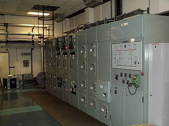
DISTRIBUTION BOARD The distribution board takes care of the power supply to the transmitters at the site. In the event of a mains electricity power failure, the distribution board provides auxiliary power from the on site generator. The distribution board is split into two, one half maintained and the other non-maintained, the maintained half is supported by an 800 kW generator. In effect, the transmitters and station are split into two. What this means in transmitter terms is that, for example, Talksport (100kW) goes to half power during a mains electricity failure, as one of the 50 kW transmitters is turned off, but the service remains on air due to the other 50 kW transmitter running as normal. There is a radiated power drop from 100 kW to 25 kW (6 dB) due to the diplexer, this is due to the way the diplexer has to divert some power into a load resistor in order to keep the on air transmitter correctly loaded. Radio 5 looses transmitter C, this means the radiated power goes from 150 kW to 66.66 kW due to the triplexer. Sunrise radio however, fortunately remain at 50 kW during a power failure. So the 800 kW generator ensures that all the services stay on air, albeit at low power for some. In broadcasting it is more important to remain on air than achieve full power, so for a few hours the radio stations put up with reduced power while the electricity supply is off. |
|
AM TRANSMITTER TECHNICAL IN BRIEF Carrier Power is the quiescent output power without any modulation. In fact the carrier power remains constant regardless of modulation. At full modulation, two thirds of the power are in the carrier, the other third in the information carrying sidebands. The 150 kW Radio 5 transmitter will output 150 kW rms with no modulation and will output 225 kW rms at 100% modulation. Peak Envelope Power (PEP) is 4 x carrier power when a transmitter is at 100 % modulation so the 150kW (carrier power) Radio 5 system is 600 kW PEP. That is four times the carrier power! Peak Mean Power (Pm) 1.5 x Carrier power at 100 % modulation so Radio 5 is 225 kW. Voltage going down the feeders at PEP is:- (Remember the aerials are 50 ohms) The 150 kW Radio 5 = 5477 volts rms. This is simply calculated from ohms law. The peak current through the feeder cable therefore will be 109.5 amps, at PEP. AM and FM transmitters are different! FM transmitters radiate at peak power all of the time regardless of modulation, but AM transmitters only radiate at peak power on envelope crests at 100% modulation. |