Portable Aerial based on the 'Slim Jim', 3/4 wave End Fed Vertical.
Here's a cute aerial for portable operation. It's a modified Slim Jim end fed aerial made out of 300-ohm ribbon feeder cable. I have not tried this aerial so I can't guarantee it's performance. I think you would have to install this aerial, on site,either onto a piece of plastic tubing or drape it down the window glass, assuming the window is church size! (A band II version will be arount 7ft long) It could also be fastened to a piece of wood, but keep the aerial clear of any metal work. It wont work laid on your car roof unless the roof is non metallic. Remember, this is a vertical aerial anyway, so it has to be installed UPRIGHT! The picture shows it horizontal, but don't use it that way! One more point is that I would not recommend the aerial be used with more than 40 watts due to the fact that a trimming capacitor is used, unless that component is rated for very high voltage and current application.
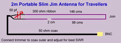
144 MHz Example
The picture above was kindly supplied to me by an amateur radio enthusiast, and as you see it shows dimensions for 2 metre ham radio use (144 MHz), which is no good to us, so I have included a revised picture below showing the dimensions for the same aerial scaled for 100 MHz. Unfortunately, it gets a bit longer in overall length!

100 MHz Example
Now, this Slim Jim is different from the usual aluminium
Slim Jim in that the feed is at the very bottom,
not tapped in a short way up. Also the bottom of this aerial is not
looped (short circuited) and the braid of the 50 ohm feeder coax feeds
the aerial via a series trimmer capacitor. This trimmer capacitor is
adjusted for lowest SWR. It should also be pointed out that the 2 cm
gap is actually a capacitance and this gap can often be made smaller
(or longer) to further improve the SWR.
Although the input arrangement is different, the type of operation remains
true to the classic Slim Jim principle. It is an end fed half wave folded
dipole matched to 50 ohms using the bottom quarter wave j-type matching
stub. The currents in the top half wave legs are in phase and reinforce
each other, but the currents in the lower quarter wave matching section
are in opposite phase and cancel. So all the radiation takes place from
the upper half wave (above the 2 cm gap) and no radiation emerges from
the bottom quarter wave section. Which is just as well because if the
bottom quarter did radiate, the radiation pattern would be ruined with
all the power going up into the sky!
Working out the length of a Slim Jim Aerial made out of 300 ohm ribbon cable
You must get the total length something like correct for
the whole aerial to be resonant and present a good SWR!
As I have already stated, I am a newcomer to making aerials out of 300
ohm ribbon cable. However, using a velocity factor of .935 (93.5%) seems
to be the way to go along with the usual calculation. Below is the formula
for the total length. Remember that the Slim Jim is in total, a three
quarter wave long aerial, although only the upper half wave radiates.
Total Aerial length = 300/frequency x .935 x .75 Please
note the answer will be in metres!
That's 300 divided by the frequency, then multiply by .935 and then
multiply again by .75
In the 100 MHz example above, the total length calculation
is 300/100 x .935 x .75 = 2.103 metres which is near enough to 210 cm.
To calculate just the upper half wave section length, do this: 300/100
x 935 x .5 = 1.4025 meters which is close to 140 cm
If the frequency of operation were to be 105 MHz, the calculation for the Slim Jim total length would be 300/105 x .935 x .75 = 2.003 metres which is 200 cm just about!